

If you have ever upgraded a CNC machine, you have probably focused on the spindle, the motor, or the controller. A lot of people do. But sometimes the reason a machine cannot hold tolerance or starts chattering is something more basic: the linear guide rails.
The problem is not that the rails are low quality. More often, the selection simply does not match the real demands of the machine. Getting this right matters because linear guide rails carry the entire weight of the work table, resist cutting forces, and keep every axis moving straight. Choose poorly, and precision issues will keep coming back no matter what else you upgrade.

How a Linear Guide Rail Works
A linear guide rail system has two main parts: the rail (the long track) and the carriage (the block that slides along it). Inside the carriage, small rolling elements-either balls or rollers-circulate along precision-ground raceways. This is completely different from old‑fashioned slide bearings, where metal slides against metal.
The rolling elements create rolling friction instead of sliding friction. The result is lower resistance, higher efficiency, and much better precision. The guide rail carries the load and maintains the reference line; the rolling elements within the carriage move along the rail's raceways to complete the linear motion. In CNC machining, this design allows the table to move smoothly under heavy load without jerking or sticking, directly affecting surface finish and tool life. For example, our HGR25-3000mm and HGR30-4000mm rails are ground to micron-level straightness, ensuring consistent motion even on long travel axes.
The Four Key Parameters You Need to Understand
1. Load Capacity
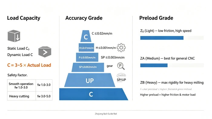
Load capacity comes in two forms: static load (C0) and dynamic load (C). Static load is the maximum force a rail can handle when the machine is stationary. Dynamic load defines the load capacity while moving and directly determines how long the rail will last.
A common mistake is assuming that if the machine works without obvious failure, the load capacity is fine. That is not accurate. You should select a rail whose rated dynamic load (C) is 3 to 5 times your actual maximum working load. For example, the HGH35CA slider has a rated dynamic load significantly higher than the HGH20CA, making it suitable for heavy‑duty gantry mills, while the HGW15CC is ideal for lighter automation tasks.
Manufacturers provide life formulas based on dynamic load ratings. The standard L10 life calculation estimates the travel distance over which 90% of identical guides will operate without fatigue failure. This means if you operate at 30% of the rated dynamic load, your life calculation delivers longer service. If you push toward 50% or more, life will decrease significantly.
2. Preload
Preload is the internal force that eliminates clearance between the rolling elements and the raceways. By using slightly oversized balls or rollers, the system creates "negative clearance," which dramatically improves stiffness and accuracy.
Preload grades generally fall into three categories:
- Light preload (Z0) : Minimal friction and heat. Best for high-speed automation, 3D printers, and semiconductor equipment.
- Medium preload (ZA / Z1) : The standard for most CNC machining. It balances rigidity, positioning accuracy, and service life.
- Heavy preload (ZB / Z2) : Maximum vibration resistance and stiffness. Used on heavy‑duty gantry mills, grinding machines, and vertical axes of machine tools.
Our HGH series and HGW series sliders are available with multiple preload options. For a typical CNC machining center, a medium preload (ZA) on a HGW30CC provides a good balance. For a high‑speed engraver, light preload (Z0) on a HGH15CA keeps friction low and temperatures under control.
A higher preload adds stiffness but also increases friction and motor load. Choose the lowest preload that still meets your rigidity needs.
3. Accuracy Grade
Accuracy grade describes the running parallelism of the guide rail: how much the carriage rises and falls as it moves.
Most brands use a standard grading system:
- C (Standard) : ≤0.02mm per meter. Suitable for material handling, welding equipment, and general automation where positioning accuracy is not critical.
- H (High) : ≤0.01mm per meter. Works for general CNC engraving, milling, and dispensing machines with positioning accuracy around ±0.02mm to ±0.05mm.
- P (Precision) : ≤0.005mm per meter. The baseline for industrial CNC machining centers, lathes, and grinding machines that need tight tolerances and high‑quality surface finishes.
- SP / UP (Super / Ultra Precision) : ≤0.003mm and below. Reserved for high-precision grinders, semiconductor inspection tools, and measurement instruments, usually paired with closed‑loop control systems.
Our HGR series rails are regularly tested by CMM and laser interferometers. For example, a HGR20-200mm Linear Guideway Rail is guaranteed to have a straightness within 0.005mm/m. If your mounting base is not precision‑ground, even an SP‑grade rail will perform like a lower‑grade model because the steel rail will simply conform to surface irregularities.
4. Ball vs. Roller
Ball and roller guides look similar, but the rolling elements make a fundamental difference.
- Ball guides use point contact between the ball and the raceway, which delivers very low friction and high travel speed. Top speeds can reach 180m/min or more. This makes them ideal for high-speed routers, laser cutters, and pick‑and‑place automation. However, point contact limits load capacity and rigidity.
- Roller guides use line contact across the length of the roller, creating a much larger contact area. This delivers roughly twice the load rating and twice the stiffness of a ball guide in the same envelope. Maximum speeds are lower because rollers are heavier and generate more friction at high rpm. Roller guides are the standard choice for heavy cutting machines, large gantry mills, and any application where cutting forces dominate.
Our HGH series and HGW series are available in both ball and roller versions. For a standard 3‑axis CNC milling machine that runs both heavy cuts and finishing passes, roller guides (e.g., HGH35CA with rollers) are usually the correct choice. For a high‑speed engraver or a plasma cutter, ball guides (e.g., HGW15CC) will perform better and cost less.
Matching the Guide Rail to Your Machine Type
Different CNC machines have different priorities. You need to match the guide rail to what your machine does.
For high‑speed machining centers and milling machines, you care about velocity, acceleration, and precision. Accuracy and low friction at speed drive the selection. A precision grade (P) and medium preload (ZA) are common here. Our HGW30CC flange sliders are often used in such applications.
For heavy‑duty gantry mills and large boring machines, the priorities shift. Rigidity under high cutting loads and the ability to support large masses are the main concerns. This usually leads to larger rail sizes (45mm or 55mm width) and heavy preload (ZB). Multiple blocks per rail or paired parallel rails also help manage overturning moments. HGH45CA and HGH55CA square sliders are typical choices here.
For smaller machines like engravers, routers, and tool changers, loads are lower and space is tight. Compact guide sizes (15mm or 20mm width) are typical. The focus is on fitting into the design while meeting load and accuracy needs. Many light‑duty CNCs use ball guides such as HGW15CC because the loads are modest and speed matters more than ultimate stiffness.
What to Do Before Installation
You can pick the perfect guide rail, but if the installation is sloppy, the performance will still be bad. Here are a few things that matter.
Mounting surface flatness. Even a slight irregularity will cause uneven load distribution, binding, or premature wear. The base must be machined to meet the manufacturer's flatness tolerance. Typical requirements range from 0.01mm/m for precision work to 0.02mm/m for standard applications.
Bolt torque and sequence. Uneven or excessive torque deforms the rail. Always use a calibrated torque wrench, tighten in the correct sequence, and work from the center outward.
Parallelism for dual‑rail systems. When using two rails, designate one as the master (fixed) rail and align the secondary rail to it. Laser tools or dial indicators help achieve parallel alignment so loads distribute evenly.
A Final Tip: Learn from Real‑World Use
Even the most careful selection process benefits from real‑world feedback. When you install new rails on a machine, pay attention to running torque, noise, and temperature during the first few days of use.
If the carriage feels unusually stiff, preload may be too high, or the rails may not be parallel. If the machine cannot hold position under load, you may need heavier preload or roller guides instead of ball guides. A leading indicator of trouble is increasing friction-if you notice that the motor has to work harder to move the table at the same feed rate, something is wrong.
Taking the time to listen and watch during initial operation helps catch mismatches before they turn into expensive failures.
Conclusion
Choosing the right CNC linear guide rail is not about picking the most expensive component or the one with the most impressive spec sheet. It is about matching the guide rail's load capacity, preload, accuracy grade, and rolling element type to what your machine actually does. When the match is right, the machine will hold tolerances, resist chatter, and run reliably for years.